It’s important that, when you install a WDG-V combustion analyzer, that you get the right angle! A tilted analyzer may not function optimally. Proper installation, at a right angle, is a must.
To start, confirm the flange size and rotational orientation on the process nozzle. Identify the size of the process flange by recording the flange dimensions. Refer to our Flange Configuration Customer Guide for an explanation of the difference between “top hole at 12:00” and two holes “straddling” the 12:00 position. Flange adapters for any size flange are available.
It may be helpful to take a picture of the flange to assist with identification. Be aware that the rotational orientation is not always apparent because of where the camera needs to be positioned to take the picture (see Figure 1). Alternatively, you can hold a small level on the top edge of the flange. This will make it obvious that the flange was installed with one hole at 12:00 or two holes straddling the 12:00 position.
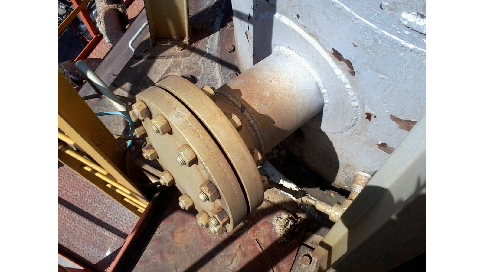
Figure 1. Is this flange installed with the top hole at 12:00 or straddled? It’s hard to tell based upon the angle of the photo.
Before identifying the flange size and rotational orientation, you need to determine how much clearance there is around the process flange. Note whether there are any obstructions nearby – such as another flange next to the one you want to use, a walkway directly below the flange, an I-beam near the side or top of the flange, etc. (Figure 2). Knowing the clearance around the flange will help ensure the analyzer fits in the location. There are solutions for many of these clearance issues. It’s good to be aware of the installation area so these can be addressed.
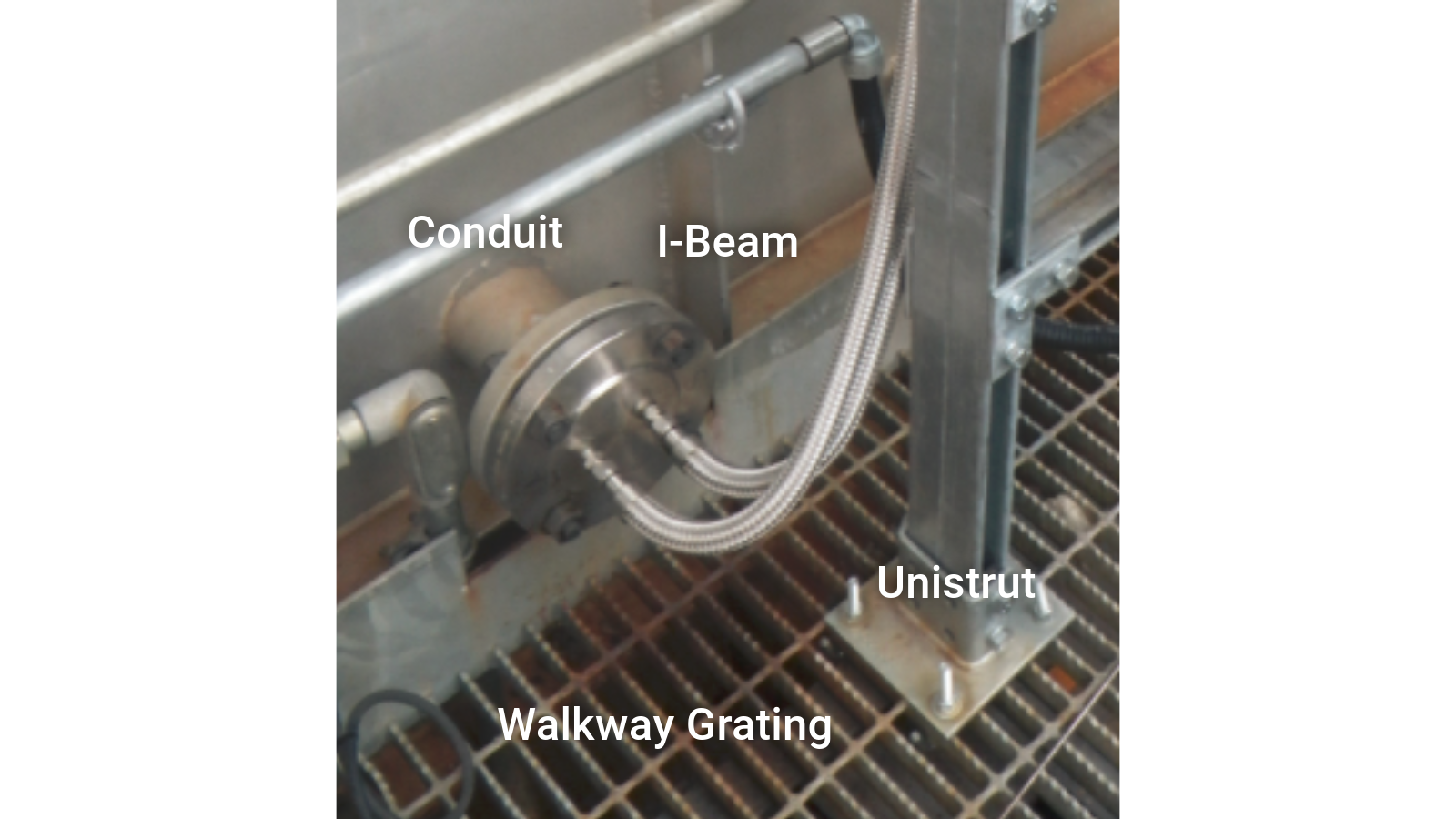
Figure 2. Things that may cause installation clearance issues.
Identifying the flange size: The edge of a flange is often stamped with the size (Figure 3). If the flange was exposed to the weather, the marking may be difficult to see. Splashing some water on the edge can make it more visible (Figure 4). The number of bolt holes can also help identify the flange size. The most common size flanges for analyzers have four bolt holes or eight bolt holes (Figure 5).
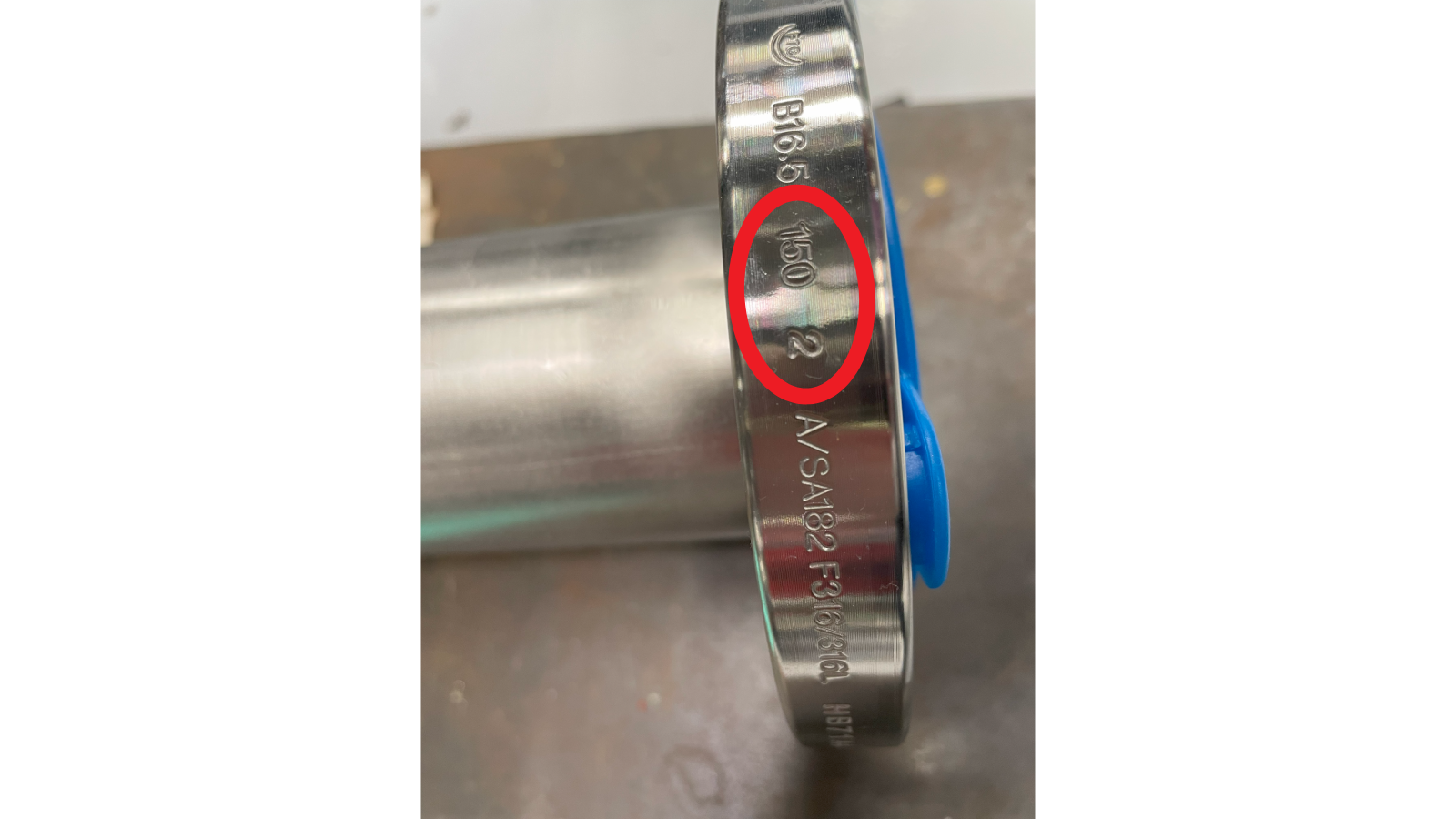
Figure 3. A clearly stamped flange size.
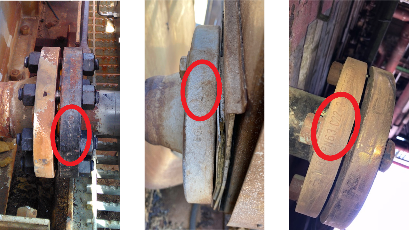
Figure 4. Weather-worn flange size stamps.
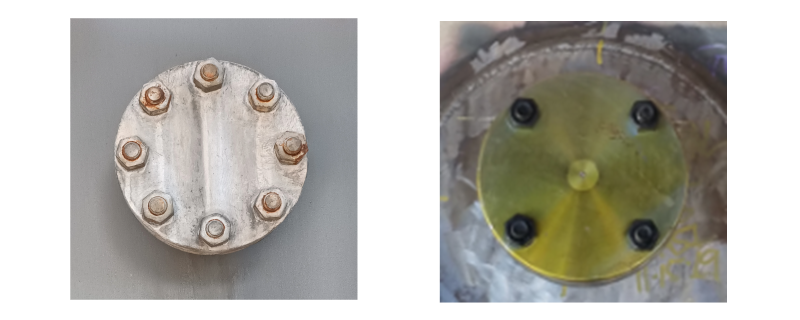
Figure 5. Determining flange size by counting bolt holes.
Once you have this information, you’re ready to install your WDG-V analyzer at the “right” angle!
For more information about the WDG-V combustion analyzer go here.